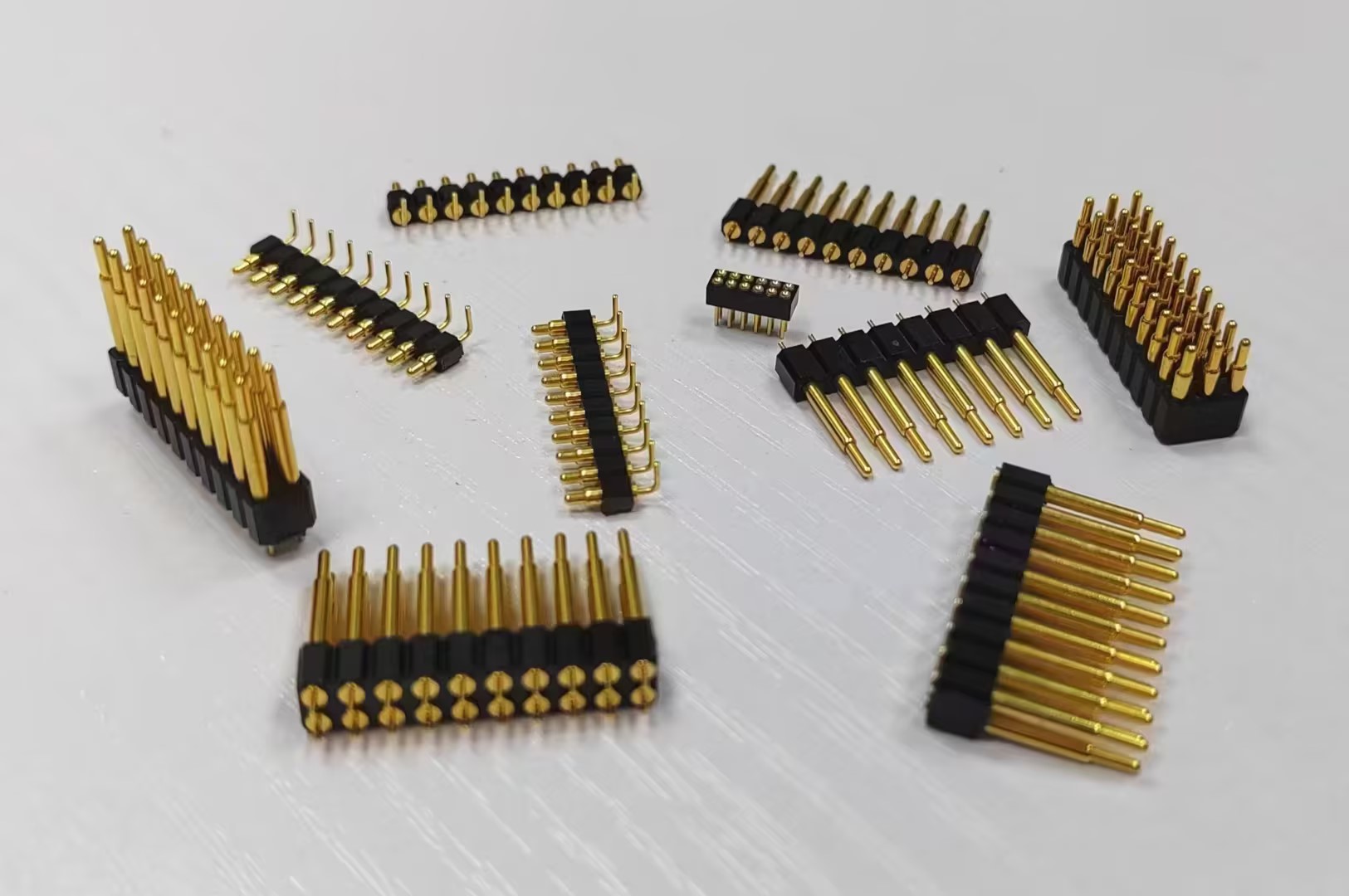
Application principle of spring loaded pogo pin
(1)pogo pin shall be arranged to make the ejection force as balanced as possible. The demoulding force required for complex structures is large, and the number of sleeves should be increased accordingly.
(2)pogo pin should be placed in effective parts, such as bones, columns, steps, metal inserts, local thick glue and other parts with complex structures. The top needles on both sides of the bone position and the column position should be arranged as symmetrically as possible. The distance between pogo pin and bone position and the position of column position are usually d = 1.5 mm. Make sure that the centerline of pogo pin on both sides of the column position passes through the center of the column position.
(3) Avoid pogopins on steps or inclined surfaces. The top surface of pogo pin should be as flat as possible. Pogo pin should be placed on structural parts with good strength.
(4) When the rubber part has deep bone position (depth ≥20mm) or it is difficult to arrange round pogopins, flat pogopins should be used. When a flat pogo pin is needed, the flat pogo pin should be in the form of an insert to facilitate processing.

(5) Avoid sharp steel and thin steel, especially the top surface of pogo pin, and do not touch the front die surface.
(6) The pogo pin layout should consider the edge spacing between pogopin and water conveyance channel, so as to avoid affecting the processing and water leakage of water conveyance channel.
(7) Considering the exhaust function of pogo pin, in order to exhaust the ejector, pogo pin should be placed in the part where vacuum is easy to form. For example, at the large plane of the cavity, although the rubber part has a small packaging force, it is easy to form a vacuum, which leads to an increase in the release force.
(8) For plastic parts with appearance requirements, pogo pin should not be placed on the design surface, and other spraying methods should also be adopted.
(9) For transparent plastic parts, pogo pin can't be placed in the parts that need light transmission.
(10) select pogo pin with larger diameter. That is to say, in the case of sufficient injection position, pogo pin with larger diameter and better size should be used.
(11)pogo pin specifications should be as small as possible. When using pogo pin, the size of pogo p in should be adjusted to minimize the size and size, and the preferred size series should be used as much as possible.
(12) The selected pogo pin shall meet the requirements of ejection strength. Pogo pin should bear great pressure when it is ejected. In order to avoid bending deformation of small pogo pin, when the diameter of pogo pin is less than 2.5mm, pogo pin should be selected.